Strain,Gauge,Bridge,Input,Process,Indicator,Model DIS978,Wilkerson Instrument

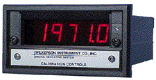
Strain Gauge (Bridge) Input Process Indicator Model DIS978


CONNECTIONS

Output - (Optional)
Output + (Optional)
NC
Input +
Input -
Shield
Alarm 1 NC (Optional)
Alarm 1 C (Optional)
Alarm 1 NO (Optional)
Alarm 2 NC (Optional)
Alarm 2 C (Optional)
Alarm 2 NO (Optional)
Power AC L1
Power AC L2
(Terminal Labeled)

1
2
3
4
5
6
7
8
9
10
11
12
13
14

Strain,Gauge,Bridge,Input,Process,Indicator,Model DIS978,Wilkerson Instrument

Strain,Gauge,Bridge,Input,Process,Indicator,Model DIS978,Wilkerson Instrument Catalogue
Strain,Gauge,Bridge,Input,Process,Indicator,Model DIS978,Wilkerson Instrument Manual


Strain,Gauge,Bridge,Input,Process,Indicator,Model DIS978,Wilkerson Instrument


Features

Strain,Gauge,Bridge,Input,Process,Indicator,Model DIS978,Wilkerson Instrument Provides 4 1/2 Digit Display, Red or Green LEDs
Strain,Gauge,Bridge,Input,Process,Indicator,Model DIS978,Wilkerson Instrument Display Calibrated in Engineering Units (psi, kg, klb, etc.) Proportional to a Strain Gauge Bridge Input
Strain,Gauge,Bridge,Input,Process,Indicator,Model DIS978,Wilkerson Instrument 0.5 mV/V to 1 V/V Input Span
Strain,Gauge,Bridge,Input,Process,Indicator,Model DIS978,Wilkerson Instrument Fully Isolated Output and/or 0, 1, or 2 Alarms (Optional)
Strain,Gauge,Bridge,Input,Process,Indicator,Model DIS978,Wilkerson Instrument Alarm Setpoints Adjustable Without Disturbing Transmitter Output
Strain,Gauge,Bridge,Input,Process,Indicator,Model DIS978,Wilkerson Instrument Fail-safe Alarm Operation
Strain,Gauge,Bridge,Input,Process,Indicator,Model DIS978,Wilkerson Instrument LED Alarm Status Indicator
Strain,Gauge,Bridge,Input,Process,Indicator,Model DIS978,Wilkerson Instrument Adjustable Deadband
Strain,Gauge,Bridge,Input,Process,Indicator,Model DIS978,Wilkerson Instrument Unlimited* Choice of Input/Output Ranges
Strain,Gauge,Bridge,Input,Process,Indicator,Model DIS978,Wilkerson Instrument Fits Standard 1/8 DIN Cutout
Strain,Gauge,Bridge,Input,Process,Indicator,Model DIS978,Wilkerson Instrument Rated NEMA-4X, Waterproof and Corrosion Resistant When Properly Installed
Strain,Gauge,Bridge,Input,Process,Indicator,Model DIS978,Wilkerson Instrument 5 + 5 Year Warranty


Description

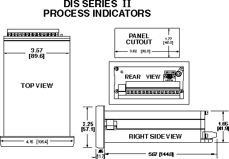
The DlS978 provides a display, optional isolated DC output voltage or current proportional to the output of a strain gauge bridge, and optional alarm setpoints. The units include filtering and conditioning to reduce susceptibility to transients and noisy operations as well as a well regulated excitation voltage for the strain gauge and a high quality differential preamplifier to condition the low level output from the bridge.  The digital display utilizes an auto-zero dual-slope integrating A/D converter for accuracy and stability.

All controls are accessible by removing a gasketed front access panel. The display controls are wide ranging so that they can be calibrated to display engineering units. Decimal point selection is made with a switch, also accessible from the front. A complete set of engineering unit labels is sent with each DIS. Once the display has been adjusted to read the correct engineering units, the alarm setpoints can be adjusted without test equipment and without disturbing the output voltage or current.

Either setpoint may be displayed by use of the SP CAL switch.  Each setpoint has a red LED to indicate alarm status. The alarms have adjustable deadbands. Terminations are made to a screw terminal connector on the rear of the case.

Typical Applications

Weight and pressure indication, control, monitoring, data acquisition and warning.

Mounting

The DIS is designed to be mounted from the front of a panel through a standard horizontal 3.62 x 1.77 inches (1/8 DIN) cutout. Two mounting camscrews secure the DIS to the panel.

Specifications

INPUT SPAN
0.5 mV/V to 1 V/V

IINPUT IMPEDANCE
200 kilohms

EXCITATION
fixed 10 V
  40 mA max load

EXCITATION STABILITY
±0.005%/°C

OUTPUT RANGE
Voltage
  select any range between ±10 V
    10 mA max load
    (min span 0.2 V)
Current
  select any range from 0 to 20 mA max
    24 V compliance**
    (min span 1 mA)

RELAY CONTACTS (spdt)
Resistive Load:
  5 A max, 150 W max,
  240 VAC max, 30 VDC max
Inductive Load:
  1/8 HP max at 120/240 VAC

SETPOINT
each alarm 0 to 100% of span

DEADBAND
0.25% to 100% of span

RESPONSE TIME
1 sec typical

ISOLATION
Output/Input
  >500 megohms
Breakdown Voltage
  >600 VAC rms

DISPLAY
Digit Size
  .56 inch LED, 4 1/2 digits, ±19999

Decimal Point
  ±1.9.9.9.9

Control Range
  Zero
    ±19999
  Span
    min span 10
    max span 20000

Display Update
  3/sec

ACCURACY
±0.1% of span

LINEARITY
Display
  ±0.01% of span

Output
  ±0.025% of span

OUTPUT RIPPLE
<0.1% of span
  (peak to peak)

COMMON MODE REJECTION
120 dB, DC to 60 Hz

OPERATING TEMPERATURE
 14°F to 140°F
-10°C to 60°C

TEMPERATURE STABILITY
±(0.02% of span +30 µV)/°C max

POWER
115 VAC ±10%, 50/60 Hz
  (4 W max)
230 VAC ±10%, 50/60 Hz
  (4 W max)

* Within specified range limits.

** Compliance:  The sum of the voltage drops in the output loop cannot exceed 24 V at rated current 
    (1200 ohms at 20 mA).